STEMCO es muy consciente del papel que desempeña en la seguridad. La seguridad del producto está integrada en el producto desde el diseño inicial, se considera durante todos los procesos de fabricación y se tiene en cuenta en la instalación del producto. La tuerca del eje Pro-Torq está diseñada para abordar posibles modos de falla y se fabrica con estándares de alta calidad constante como parte del enfoque de STEMCO en productos y prácticas seguras.
El propósito de este consejo técnico es informar a los clientes sobre los métodos de instalación adecuados para la tuerca del eje del eje Pro-Torq. Este procedimiento producirá consistentemente un ajuste del rodamiento de 0,001" a 0,005" de juego axial.
Haremos referencia a los siguientes archivos PDF de STEMCO:
- Procedimiento de instalación de sujetadores de eje Pro-Torq y ajuste de cojinetes
- Cuadro mural de instalación de Pro-Torq
- Intervalo de reemplazo de Pro-Torq Keeper
- Catálogo STEMCO-TQM
Procedimiento de instalación y ajuste del cojinete de rueda
PASO 1
Retire el guardián de la tuerca.
- Utilice un destornillador pequeño para hacer palanca con cuidado en el brazo del retén de la ranura socavada de cada lado hasta que se suelte el retén.
- Sostenga firmemente el conjunto de tuerca ProTorq con una mano. Ubique el pulgar sobre la función pestaña/Dplano.
- Coloque la hoja de un destornillador de punta plana en la ranura ubicada en la pata del retenedor. Nota: NO coloque la hoja del destornillador en ningún otro lugar a lo largo de la pata del retenedor.
- Pase la hoja del destornillador más allá de la pata del retenedor, hasta que esté en contacto con la tuerca. Esto se puede lograr haciendo palanca en el destornillador mientras lo mueve hacia adelante y hacia atrás. Asegúrese de que la hoja esté en contacto con la superficie (como se muestra a continuación) y no con los dientes de la tuerca.
- Haga palanca en la pata del retén hasta que salga de la ranura de la tuerca.
- Cambie de mano y repita para quitar la otra pierna del portero. Asegúrese de sujetar el retenedor firmemente con el pulgar, esto evitará que el retenedor salte de la tuerca hacia el usuario una vez que retire la segunda pata.
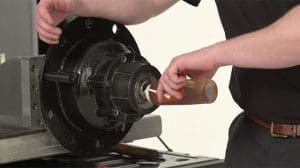
PASO 2
Enrosque la tuerca en el eje hasta que quede apretada con la mano contra el cojinete.
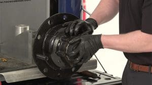
PASO 3
Asentar el rodamiento
Solo con maza o maza/tambor, use una llave dinamométrica:
- Apriete el sujetador a 200 pies-libras. Haga girar la rueda al menos una rotación completa.
- Apriete la tuerca a 200 pies-libras. Haga girar la rueda al menos una rotación completa.
- Apriete la tuerca a 200 pies-libras.
- Retire la tuerca hasta que esté suelta.
- Con buje/tambor/ruedas:
- Apriete la tuerca a 200 pies-libras mientras la rueda esté girando.
- Retire la tuerca hasta que esté suelta.
ETAPA 4
Ajustar el rodamiento
Solo con maza o maza/tambor, use una llave dinamométrica:
- Apriete la tuerca a 100 pies-libras. Haga girar la rueda al menos una rotación completa.
- Apriete la tuerca a 100 pies-libras. Haga girar la rueda al menos una rotación completa.
- Apriete la tuerca a 100 pies-libras.
- Retire la tuerca de una marca de la cara elevada (según la tabla)
Con maza/tambor/ruedas, utilice una llave dinamométrica:
- Apriete la tuerca a 100 pies-libras mientras la rueda esté girando.
- Retire la tuerca de una marca de la cara elevada (según la tabla)
PASO 5
instalar el guardián
- Inserte la lengüeta de retención en la ranura socavada de la tuerca y enganche la lengüeta del chavetero en el chavetero del eje. Inserte la pestaña de retención con el lado naranja hacia afuera.
- Enganche los dientes coincidentes.
- Comprimir e insertar el brazo del portero.
Para tuerca del eje de dirección 448-4836, 448-4839, 448-4840, 448-4863, 448-4864 y 448-4865:
- Alinee la parte plana del retenedor con la parte plana fresada del eje e inserte la lengüeta del retenedor individual en la ranura recortada de la tuerca. Inserte la pestaña de retención con el lado naranja hacia afuera.
- Enganche los dientes coincidentes
- Comprima e inserte los brazos de retención, uno a la vez, en la ranura socavada con un destornillador pequeño.
PASO 6
Inspeccionar la instalación
- No seguir estas instrucciones podría provocar que la rueda se salga y provocar lesiones corporales.
- Asegúrese de que la lengüeta de retención y los brazos de retención estén completamente asentados en la ranura recortada.
- Inspeccione la espiga del cuñero para asegurarse de que no entre en contacto con la parte inferior del cuñero. Si existe contacto, notifique inmediatamente a su representante de PRO-TORQ.
PASO 7
Juego final aceptable
- El indicador de cuadrante debe fijarse al cubo o al tambor de freno con su base magnética.
- Ajuste el indicador de cuadrante de modo que su émbolo esté contra el extremo del eje con su línea de acción aproximadamente paralela al eje del eje.
- Si no es posible montar el eje, el indicador de cuadrante debe fijarse al cubo y alinearse para indicar en el eje.
- Sujete el conjunto de rueda o cubo en las posiciones de las 3 y las 9 en punto.
- Empuje y tire del conjunto del extremo de la rueda hacia adentro y hacia afuera mientras hace oscilar la rueda aproximadamente 45 grados.
- Deje de oscilar el cubo para que la punta del indicador de cuadrante esté en la misma posición que estaba antes de que comenzara la oscilación.
- Lea el juego longitudinal del rodamiento como el movimiento total del indicador.
*El juego final aceptable es .001″ – .005″
Si desea obtener más información sobre nuestra tuerca del eje del eje STEMCO Pro-Torq, visite nuestro página del producto.
Para acceder a nuestra biblioteca completa de consejos técnicos, haga clic aquí.
Para artículos detallados que cubren noticias y tendencias de la industria, productos destacados, estudios de casos, opiniones de clientes y temas de "liderazgo intelectual" de profesionales de STEMCO, visite El blog de la timonera.