STEMCO est très consciente du rôle qu'elle joue en matière de sécurité. La sécurité du produit est intégrée au produit dès la conception initiale, prise en compte tout au long des processus de fabrication et prise en compte lors de l'installation du produit. L'écrou de broche d'essieu Pro-Torq est conçu pour répondre aux modes de défaillance potentiels et est fabriqué selon des normes de qualité constamment élevées dans le cadre de l'accent mis par STEMCO sur des produits et des pratiques sûrs.
Le but de cette astuce technique est d'informer les clients des méthodes d'installation appropriées pour l'écrou de broche d'essieu Pro-Torq. Cette procédure aboutira à la production constante d'un réglage de roulement de 0,001″ à 0,005″ de jeu final.
Nous ferons référence aux PDF STEMCO suivants :
- Procédure d'installation des fixations d'essieu Pro-Torq et réglage des roulements
- Tableau mural d'installation Pro-Torq
- Intervalle de remplacement du dispositif Pro-Torq Keeper
- Catalogue STEMCO-TQM
Procédure d'installation et réglage des roulements de roue
ÉTAPE 1
Retirez le gardien de l'écrou
- Utilisez un petit tournevis pour retirer délicatement le bras du dispositif de retenue de la rainure dégagée de chaque côté jusqu'à ce que le dispositif de retenue soit libéré.
- Tenez fermement l’ensemble d’écrou ProTorq dans une main. Localisez le pouce sur la fonction onglet/Dflat.
- Placez la lame d'un tournevis à tête plate dans la fente située sur le pied du support. Remarque : NE placez PAS la lame du tournevis à un autre endroit le long du pied du support.
- Passez la lame du tournevis au-delà de la patte du gardien, jusqu'à ce qu'elle soit en contact avec l'écrou. Cela peut être accompli en faisant levier sur le tournevis tout en le déplaçant d'avant en arrière. Assurez-vous que la lame est en contact avec la surface (comme indiqué ci-dessous) et non en contact avec les dents de l'écrou.
- Soulevez le pied du gardien jusqu'à ce qu'il soit hors de la rainure de l'écrou.
- Changez de main et répétez l’opération pour retirer l’autre jambe du gardien. Assurez-vous de tenir fermement la gâche avec le pouce, cela empêchera la gâche de sortir de l'écrou vers l'utilisateur une fois la deuxième patte retirée.
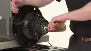
ÉTAPE 2
Vissez l'écrou sur l'essieu jusqu'à ce qu'il soit serré à la main contre le roulement.
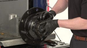
ÉTAPE 3
Placer le roulement
Avec moyeu ou moyeu/tambour uniquement, utiliser une clé dynamométrique :
- Serrez la fixation à 200 pi-lb. Faites tourner la roue au moins un tour complet.
- Serrez l'écrou à 200 pi-lb. Faites tourner la roue au moins un tour complet.
- Serrez l'écrou à 200 pi-lb.
- Retirez l'écrou jusqu'à ce qu'il soit desserré.
- Avec moyeu/tambour/roues :
- Serrez l'écrou à 200 lb-pi pendant que la roue tourne.
- Retirez l'écrou jusqu'à ce qu'il soit desserré.
ÉTAPE 4
Ajuster le roulement
Avec moyeu ou moyeu/tambour uniquement, utiliser une clé dynamométrique :
- Serrez l'écrou à 100 pi-lb. Faites tourner la roue au moins un tour complet.
- Serrez l'écrou à 100 pi-lb. Faites tourner la roue au moins un tour complet.
- Serrez l'écrou à 100 pi-lb.
- Retirez l'écrou d'une marque de face surélevée (selon le tableau)
Avec moyeu/tambour/roues, utilisez une clé dynamométrique :
- Serrez l'écrou à 100 pi-lb pendant que la roue tourne.
- Retirez l'écrou d'une marque de face surélevée (selon le tableau)
ÉTAPE 5
Installer le gardien
- Insérez la languette de maintien dans la rainure en contre-dépouille de l'écrou et engagez la languette de la rainure de clavette dans la rainure de l'essieu. Insérez la languette de maintien avec le côté orange vers l'extérieur.
- Engagez les dents correspondantes.
- Comprimer et insérer le bras du gardien
Pour l'écrou de fusée de direction 448-4836, 448-4839, 448-4840, 448-4863, 448-4864 et 448-4865 :
- Alignez le plat du gardien avec le méplat fraisé sur la broche et insérez la languette du gardien unique dans la rainure en contre-dépouille de l'écrou. Insérez la languette de maintien avec le côté orange vers l'extérieur
- Engagez les dents homologues
- Comprimez et insérez les bras de maintien, un à la fois, dans la rainure dégagée à l'aide d'un petit tournevis.
ÉTAPE 6
Inspecter l'installation
- Le non-respect de cette instruction pourrait entraîner le détachement de la roue et provoquer des blessures corporelles.
- Assurez-vous que la languette de retenue et les bras de retenue sont entièrement insérés dans la rainure en contre-dépouille.
- Inspectez la tige de la rainure de clavette pour vous assurer qu’elle n’entre pas en contact avec le bas de la rainure de clavette. Si un contact existe, informez-en immédiatement votre représentant PRO-TORQ
ÉTAPE 7
Jeu final acceptable
- Le comparateur à cadran doit être fixé au moyeu ou au tambour de frein avec sa base magnétique.
- Ajustez le comparateur à cadran de manière à ce que son piston soit contre l'extrémité de la broche avec sa ligne d'action approximativement parallèle à l'axe de la broche.
- Si le montage sur la broche n'est pas possible, le comparateur à cadran doit être fixé au moyeu et aligné pour indiquer sur la broche.
- Saisissez l'ensemble roue ou moyeu aux positions 3 heures et 9 heures.
- Poussez et tirez l'ensemble d'extrémité de roue vers l'intérieur et vers l'extérieur tout en faisant osciller la roue d'environ 45 degrés.
- Arrêtez de faire osciller le moyeu afin que la pointe du comparateur à cadran soit dans la même position qu'elle était avant le début de l'oscillation.
- Lisez le jeu final du roulement comme le mouvement total de l'indicateur.
*Le jeu final acceptable est de 0,001″ à 0,005″
Si vous souhaitez plus d'informations sur notre écrou de broche d'essieu STEMCO Pro-Torq, visitez notre page produit.
Pour accéder à notre bibliothèque complète de conseils techniques, Cliquez ici.
Pour des articles approfondis couvrant l'actualité et les tendances du secteur, les produits phares, les études de cas, les informations sur les clients et les sujets de « leadership éclairé » rédigés par des professionnels de STEMCO, visitez Le blog de la timonerie.